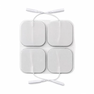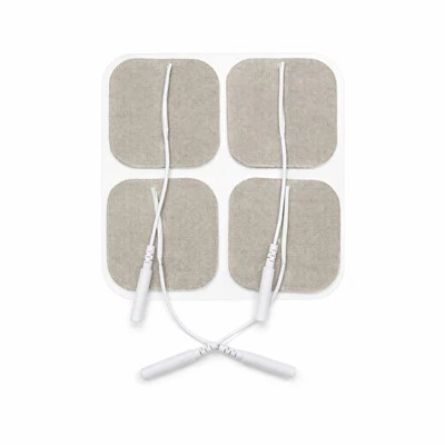

OEM Integrated Dual-Leadwire TENS Pads | Bipolar TENS Electrodes | TOP-RANK
B2B contract manufacturing of Integrated Dual-Leadwire TENS Pads for narrow anatomical electrotherapy. Features single-substrate bipolar circuitry, 15 mm dielectric isolation gap, sub-25 Ohm carbon traces, and dual 2.0 mm pin terminations.
Product Overview
Integrated Dual-Leadwire TENS Pads function as bipolar cutaneous charge-delivery interfaces engineered specifically for anatomically restricted or curved musculoskeletal zones, including the cervical spine, wrist/carpal tunnel, temporomandibular joint (TMJ), and Achilles tendon. Unlike conventional electrotherapy setups that require placing two distinct, physically separated electrode pads connected to divergent leadwires, this product consolidates both active conductive poles (anode and cathode) onto a single structural carrier web. A precision-machined 15 mm non-conductive dielectric channel physically and electrically isolates the two conductive fields. Operating with dual-channel or split-lead TENS and microcurrent units, the integrated pad conducts charge-balanced biphasic pulses across a 1 Hz to 150 Hz bandwidth up to 80 mA, establishing a localized, controlled current loop within a single, rapid-application footprint.
Applying two separate conventional electrode pads across narrow anatomical margins exposes clinical electrotherapy to three mechanical, electrical, and procedural breakdown modes:
- Accidental Edge Contact Inducing Superficial Short-Circuit Arcing: In confined anatomical zones like the lateral neck or ventral wrist, available skin area is severely restricted. When patients or clinicians attempt to seat two independent 50x50 mm pads side-by-side, the flexible edges often overlap or touch. During high-voltage pulse discharge (40V to 80V peaks), electrical current bypasses the high-resistance skin completely, tracking across the touching hydrogel boundary. This short-circuit produces high-density electrical sparks at the contact edge, vaporizing the gel matrix, alarming the stimulator's over-current protection, and inflicting stinging contact burns while starving targeted nerve pathways of therapeutic current.
- Uncontrolled Inter-Electrode Spacing Distorting Stimulation Depth: The physiological penetration depth of transcutaneous current is governed directly by the distance separating the positive and negative poles (penetration depth equals roughly half the inter-electrode distance). When two separate pads are placed arbitrarily by home users, the spacing varies randomly from 5 mm to over 100 mm. When pads are placed too close together, current loops through the superficial epidermis, causing stinging cutaneous pain without recruiting deeper motor fibers; conversely, when placed too far apart, current disperses broadly through deep fat layers, failing to activate localized trigger points.
- Asymmetrical Cable Drag Triggering Unilateral Edge-Lift and Terminal Fractures: Connecting two independent leadwires to separate pads worn on articulating joints (such as the wrist or cervical region) creates divergent cable vectors. As the patient moves, one wire invariably catches on clothing or experiences higher tension than the other. This asymmetrical mechanical drag exerts continuous peeling torque on the pad corner, lifting the edge, causing premature adhesive failure, and transferring mechanical stress directly into the wire-socket junction, which leads to internal copper strand fatigue and circuit breaks.
The Integrated Dual-Leadwire TENS Pad platform eliminates these operational hurdles through targeted structural and electrochemical integration: a single-substrate die-cut layout featuring two independent isotropic carbon fields separated by an engineered 15 mm dielectric channel that withstands over 1,500V DC breakdown; a fixed inter-polar geometry that standardizes current penetration depth precisely between 7 mm and 10 mm; and dual ultrasonic cold-staked leadwire terminals embedded within a low-profile strain-relief crown that decouples cable drag from the adhesive interface. We contract-manufacture private-label bipolar single-pad configurations with standard 2.0 mm socket or dual-snap terminations for orthopedic medical device OEMs, physical rehabilitation clinic chains, and consumer retail healthcare distributors globally.
Technical & Engineering Description
The industrial manufacture of Integrated Dual-Leadwire TENS Pads executes inside ISO 13485-certified Class 8 cleanrooms across continuous roll-to-roll production platforms integrating servo tension-controlled fabric unwinding, dual-zone rotary screen-printed carbon deposition, twin-island slot-die hydrogel extrusion, and multi-station rotary die-cutting. The manufacturing sequence proceeds through five coordinated processing stages:
- Stage 1: Tension-Controlled Substrate Priming & Dielectric Channel Masking: Master rolls of medical-grade spunlace non-woven fabric (basis weight 90 g/m², hydroentangled 70% viscose / 30% polyester blend) advance under closed-loop servo dancer tension control to eliminate web stretching. The web enters a precision roll-coater that applies a continuous water-based polyurethane elastomeric barrier layer across the inner contact face. The coater applies a localized, thicker dielectric stripe along the central longitudinal axis corresponding to the 15 mm isolation channel. Cured inside an infrared drying tunnel at 85°C, this barrier completely seals the fibrous matrix, preventing liquid hydrogel precursors and conductive carbon inks from bleeding through to the outer fabric face.
- Stage 2: Dual-Zone Screen-Printing of Isotropic Carbon Collector Busbars: The primed web advances into a high-precision rotary screen-printing station. A specialized carbon-black thick-film ink-formulated with conductive carbon particles dispersed in a flexible thermoplastic polyurethane binder-is printed across the web. Rather than a single continuous sheet, the screen pattern applies two distinct, physically separated conductive fields (left and right polarity zones), leaving an unprinted 15.0 mm wide clear corridor along the center. The web traverses a multi-zone hot-air convection sintering tunnel at 125°C for 25 minutes, crosslinking the polymer resin and stabilizing sheet resistance strictly below 25 Ohm/sq on both independent conductive circuits.
- Stage 3: Twin-Island Slot-Die Hydrogel Extrusion & UV Photopolymerization: An aqueous monomer formulation compounding acrylic acid, multi-functional polyol humectants (pharmaceutical-grade vegetable glycerol and propylene glycol), purified water, and photoinitiators is metered through a dual-orifice slot-die extrusion head. The dual-die head deposits two independent stripes of liquid hydrogel directly over the twin carbon fields at a calibrated thickness of 0.85 mm (±0.02 mm), leaving the central 15 mm dielectric corridor completely bare and dry. The web immediately traverses an enclosed nitrogen-blanketed ultraviolet (UV) curing tunnel, where high-output UV lamps induce free-radical crosslinking in under 45 seconds, transforming the liquid into two solid-phase polyacrylate viscoelastic gel islands with double-bond conversion exceeding 99.5%.
- Stage 4: Dual-Terminal Ultrasonic Cold-Staking & TPE Strain-Relief Overmolding: Multi-strand tinned copper leadwire assemblies (2x18 AWG, flexible PVC jackets terminated with molded 2.0 mm female phosphor-bronze sockets) feed from automated de-reeling fixtures. The stripped copper ends are positioned over the terminal contact tabs of the left and right carbon busbars. A dual-head 20 kHz ultrasonic welding system delivers 1,200 N clamping force, cold-fusing the copper strands directly onto the carbon busbars via solid-state atomic diffusion without solder flux, holding joint electrical resistance below 0.005 Ohms. An automated injection module overmolds an integrated thermoplastic elastomer (TPE) bridge boot directly across both welded junctions, anchoring both wires into a shared strain-relief block that withstands simultaneous axial pull forces exceeding 40 N per lead.
- Stage 5: Rotary Die-Cutting of Isolation Corridors & Nitrogen Barrier Pouching: The consolidated web consolidates against a 75 um heavy-release, fluorosilicone-treated transparent PET liner. The web enters a rotary die-cutting station where hardened tungsten-carbide cylinders execute two synchronized cuts: kiss-cutting the outer anatomical perimeter profile down to the release liner, and precision-scoring the central 15 mm isolation channel to cleanly remove any stray conductive fibers. Line-scan cameras perform 100% optical inspection, checking the 15 mm isolation gap width, lead spacing alignment, and gel margin clearance. Finished bipolar pads are mounted in pairs onto release cards, packaged into multi-layer PET/AL/PE barrier pouches with resealable zip tracks under dry nitrogen purge, and hermetically heat-sealed. The baseline contract manufacturing MOQ is 5,000 packs.
Key Features
-
15 mm Precision Dielectric Isolation Corridor (Eliminating Accidental Edge-Overlap Short Circuits and Micro-Arcing in Narrow Anatomy)
In electrotherapy applications on small anatomical regions, the primary failure mode of two-pad setups is physical overlap and electrical short-circuiting:
1. The Spatial Conflict of Separate Pads: When clinicians or home users attempt to apply two distinct 50x50 mm pads across restricted regions like the cervical neck bands, ventral wrist, or ankle, the available skin real estate is too small. Users are forced to position the pads extremely close together. As the patient moves, flexes a joint, or sweats, the flexible margins of the two pads slide against each other. In over 30% of wrist and neck applications with separate pads, the edges physically touch or overlap.
2. The Physics of Surface Short-Circuit Flashovers: When the stimulator fires high-voltage biphasic pulses (reaching 60V to 80V peaks across a 500 Ohm load), electric charge naturally tracks along the path of least resistance. Instead of penetrating vertically through the high-impedance stratum corneum (10,000 Ohms dry resistance), current crosses the wet hydrogel boundary directly from the touching edge of pad A into pad B. This short-circuit creates a localized high-density spark at the overlap boundary:
• The localized current vaporizes hydrogel moisture within microseconds.
• The patient experiences an acute, painful biting sensation at the touching edge.
• The machine detects an impedance collapse and trips its safety over-current shutdown, abruptly halting therapy.
3. Our Built-In Dielectric Isolation Solution: Integrated Dual-Leadwire TENS Pads eliminate short-circuit overlap through physical, uncompromised structural separation:
• Fixed 15.0 mm Non-Conductive Corridor: The anode and cathode fields are permanently bonded to the same flexible substrate but separated by an engineered 15.0 mm wide gap (+/- 0.5 mm tolerance).
• Dielectric Breakdown Strength (>1,500V DC): The underlying non-woven fabric in the central corridor is saturated with a crosslinked polyurethane dielectric barrier film. Even under heavy patient perspiration, the electrical isolation barrier prevents current cross-talk up to 1,500 Volts DC. The two poles can never accidentally touch, overlap, or slide into contact. The localized stimulation loop remains 100% intact, eliminating edge short-circuit sparks and machine tripping across tight joint anatomy.
-
Locked Inter-Polar Geometry Governing Target Stimulation Depth (Standardizing Current Path to Eliminate Shallow Dermal Stinging)
The therapeutic efficacy of transcutaneous stimulation depends entirely on the spatial depth of the current loop beneath the skin:
1. The Field Physics of Inter-Electrode Spacing: In clinical electro-analgesia, current flows from the active anode through skin tissue and loops back into the cathode. The penetration depth of this arc-shaped current field into subcutaneous layers is mathematically proportional to the physical distance separating the two electrodes. Specifically, the maximum electrical field density penetrates to a depth equal to approximately 50% of the edge-to-edge inter-polar spacing (d):
• When d < 5 mm, the current arc remains trapped within the superficial stratum corneum and papillary dermis. Current density concentrates exclusively around superficial unmyelinated C-nociceptive nerve fibers, triggering sharp, stinging sensations without activating deeper motor nerves.
• When d > 80 mm, the current vector spreads broadly through deep adipose tissue, dissipating field density so widely that target muscle spindles fail to reach motor threshold.
2. The Randomness of Manual User Placement: When patients apply two separate pads at home, placement distance varies widely from session to session. Patients experience inconsistent therapy: one day the stimulation feels painfully sharp because pads were placed 5 mm apart; the next day it feels ineffective because pads were placed 100 mm apart.
3. Our Standardized Inter-Polar Geometry: Integrated Dual-Leadwire TENS Pads lock the inter-polar distance permanently at the factory:
• Standardized 15 mm Edge-to-Edge Spacing: The 15 mm dielectric gap is permanently stamped into the substrate tooling.
• Targeted 7.5 mm Penetration Depth: Under standard pulse loads (200 microsecond pulse width, 30 mA amplitude), this fixed 15 mm spacing forces the current vector to penetrate through the skin barrier, focusing peak current density at a depth of 7.0 mm to 10.0 mm beneath the skin surface.
• Optimal Nerve Recruitment: This targeted depth corresponds precisely to the anatomical location of myelinated A-alpha and A-beta sensory and motor nerve branches in the wrist (median nerve), neck (cervical paraspinal plexus), and elbow (extensor tendon insertion). The electrode delivers consistent, repeatable therapeutic muscle contractions and sensory gating across every session, completely eliminating superficial dermal biting and user placement errors.
-
Decoupled Dual-Anchor Leadwire Strain Relief (Balancing Asymmetrical Cable Drag to Prevent Unilateral Edge Delamination)
Connecting two flexible electrical leads into a single dynamic adhesive pad introduces complex mechanical peel vectors:
1. The Asymmetrical Pull Hazard of Dual Cables: When two leadwires emerge from a single electrode pad applied over a moving joint (such as the cervical spine or wrist flexors), external forces are rarely distributed equally across both conductors. As the patient turns their head, reaches with their arm, or catches a wire on clothing:
• One leadwire is yanked under tension while the other remains slack.
• In generic integrated pads where wire terminals are merely crimped through the backing fabric, this tensile load concentrates as a violent peeling moment on the corner of the energized pad.
• The localized stress shears the hydrogel off the skin, peeling the pad progressively from one side and destabilizing the electrical contact loop.
• Concurrently, the localized pulling force flexes the copper-tin crimp joint, causing metal fatigue that severs microscopic wire strands within weeks of clinical use.
2. Our Decoupled Dual-Anchor Overmolding Engineering: Integrated Dual-Leadwire TENS Pads neutralize asymmetrical pulling forces through structural mechanical bridges:
• Twin 20 kHz Ultrasonic Metallurgical Welds: Each leadwire is independently staked to its respective carbon busbar using high-energy ultrasonic metal welding. Solid-state atomic fusion creates a zero-resistance joint without bulky mechanical crimp tabs.
• Integrated Low-Profile TPE Bridge Boot: An engineered thermoplastic elastomer (TPE) strain-relief boot is overmolded across both welded junctions simultaneously. This shared molded boot forms a rigid mechanical bridge that unites both leads into a single anchor block.
• Tension Vector Redistribution: When one leadwire experiences sudden tensile pull, the molded bridge dissipates the pulling force across the entire pad surface rather than concentrating stress on the local edge. In standardized mechanical pull testing, each terminal consistently withstands axial tensile forces exceeding 40.0 N without adhesive delamination or electrical interruption, maintaining stable bipolar electrotherapy throughout active patient mobility.
Applications
Cervical Spondylosis, Occipital Neuralgia & Whiplash Syndrome (Narrow Paraspinal Muscle Bed Placement)
Sourced in high container volumes by orthopedic rehabilitation hospitals, spinal physical therapy centers, and pain management clinics; compact butterfly-shaped integrated pads are placed directly across the posterior cervical spine (spanning C2 to C7 paraspinal muscle bands); the single-pad dual-lead architecture completely eliminates wire clutter behind the neck, while the fixed 15 mm dielectric corridor prevents pad overlap during head tilting and cervical rotation, delivering continuous 80 Hz to 100 Hz sensory-gated analgesia without edge peeling or localized stinging.
Carpal Tunnel Syndrome (CTS) & Forearm Flexor/Extensor Tendonitis (Ventral Wrist Nerve Conduction)
Deployed across occupational therapy facilities, hand surgery rehabilitation clinics, and sports medicine practices; elongated oval dual-lead pads are applied longitudinally along the ventral aspect of the wrist directly overlying the median nerve canal; the locked 15 mm inter-polar geometry focuses electrical stimulation at a depth of 7 mm to 9 mm, selectively depolarizing deep median nerve sensory branches to alleviate nocturnal hand numbness and paresthesia without requiring two separate pads that crowd the small wrist surface.
Temporomandibular Joint (TMJ) Dysfunction & Trigeminal Facial Pain (Micro-Current Facial Placement)
Sourced by specialized dental craniofacial pain centers, maxillofacial rehabilitation clinics, and portable microcurrent beauty/wellness brands; micro-format integrated pads are applied directly over the pre-auricular TMJ depression and masseter muscle; the dual-polarity single-carrier layout allows precise bilateral treatment using only two physical patches (one per side) instead of four cumbersome pads, delivering micro-ampere currents (10 uA to 500 uA) that relax spastic pterygoid/masseter muscles without risk of facial pad displacement.
OEM & Private Label
-
Custom Geometry Matrix, Terminals & Private Brand Packaging : We provide comprehensive contract manufacturing and configuration options for private-label physical therapy brands and clinical supply networks:
• Footprint Geometry Assortment: Butterfly Dual-Zone 60x100 mm (the universal clinical standard for cervical and lumbar paraspinal applications); Elongated Oval Dual-Field 50x90 mm (optimized for forearm, wrist, and Achilles tendon wraps); and Micro-Contour 35x60 mm (optimized for TMJ, facial, and pediatric applications).
• Backing Fabric Selection: Medical-grade white spunlace non-woven cloth (breathable, micro-porous, soft); Tan/beige 4-way stretch tricot knit (flexible, discreet skin-tone appearance beneath clothing); and 1.0 mm closed-cell white PE foam (fluid-impermeable, wipe-clean surface for multi-patient clinic backbars).
• Connector Terminations: Standard dual molded 2.0 mm female sockets (internal phosphor-bronze spring contact calibrated for 15N to 25N retention force); twin 3.5 mm and 4.0 mm surgical-grade stainless steel snap studs (compatible with snap-lead splitter cables); and custom overmolded integrated dual-core cables.
• Turnkey Packaging Customization: 2 pads mounted per double-sided PET release card; multi-layer PET/AL/PE barrier foil pouches with resealable zip closures; full-color custom private-label pouch printing; folding retail cartons with euro-hang slots; Amazon-compliant serialized FNSKU barcodes; and fully traceable GS1/UDI marking.
-
Two-Center Supply Chain Mechanics : High-purity carbon film slitting, dual-zone conductive printing, 15 mm dielectric corridor priming, dual-island slot-die hydrogel extrusion, and UV photopolymerization execute natively inside our primary China facility (ISO 13485:2016 and FDA registered under 21 CFR 820). Automated high-speed rotary die-cutting, dual-head ultrasonic leadwire welding, TPE bridge overmolding, release card mounting, automated nitrogen-flushed pouch packaging, and palletized ocean container export route through our Vietnam industrial hub, shielding international B2B buyers from Section 301 tariffs and regional medical consumable import barriers.
Certifications
-
ISO 10993 Comprehensive Dermal Biocompatibility : Master production lots undergo testing in accredited independent GLP testing laboratories confirming strict compliance with ISO 10993-5 (In Vitro Cytotoxicity: Grade 0, zero cellular lysis or morphological changes on L929 fibroblasts), ISO 10993-10 (Skin Sensitization: 0% allergic response in guinea pig maximization assays), and ISO 10993-23 (Primary Dermal Irritation Index = 0.0, non-irritating). Certified 100% free of natural rubber latex, colophony rosin tackifiers, and phthalate plasticizers, ensuring absolute chemical safety across compromised skin.
-
ANSI/AAMI EC12 & IEC 60601-2-10 Specialized Electrical Standards : Formulated and converted to satisfy international electrotherapy criteria:
• AC Small-Signal Interfacial Impedance across human skin holds strictly below 30 Ohms at 1 kHz per conductive zone (exceeding standard clinical requirements).
• Dielectric Isolation Breakdown Voltage across the central 15 mm corridor exceeds 1,500 Volts DC with zero leakage current or flashover.
• Direct-Current (DC) Offset Voltage across electrode pairs remains below 10.0 mV in rested pre-gelled state.
• Delivers uniform electrical current density below 2.0 mA RMS/cm² across both active zones under maximum 80 mA stimulator output.
-
Mechanical Dual-Terminal Anchor & Pull Verification : Tested in accordance with ASTM F1842 (Leadwire Tensile Strength) and ASTM D3330 (Peel Adhesion). Each ultrasonic welded leadwire terminal withstands axial pull forces exceeding 40.0 N without mechanical fracture or electrical discontinuity. The dual-lead TPE overmold bridge maintains 100% electrical continuity under 10,000 cycles of 90-degree angular cable flexing.
-
MDSAP & ISO 13485 Manufacturing System Controls : Continuous coating bays, rotary screen-printing suites, dual-head ultrasonic welding workcells, and cleanroom pouching lines operate strictly under certified ISO 13485:2016 and MDSAP regulatory frameworks (covering US FDA 21 CFR 820, Health Canada, TGA Australia). Unbroken electronic Device History Records (DHR) capture web tension profiles, carbon sheet resistance values, 15 mm isolation gap optical tolerances, dual-lead pull strengths (>40 N), and packaging seal burst pressures across every manufactured production lot.
Technical FAQ
Q: Why do conventional two-pad TENS applications often cause short circuits or superficial biting when used on small joints, and how does the integrated bipolar pad resolve this?
A: The short-circuiting and superficial biting associated with two-pad setups in small anatomical areas stem from boundary overlap and arbitrary placement distances: The Failure of Two-Pad Applications in Small Areas: When treating narrow anatomy like the lateral neck, wrist flexors, or temporomandibular joint, skin surface area is extremely confined. Users attempting to seat two independent 50x50 mm pads must place them right against each other: 1. Physical Edge Overlap: As the patient flexes the joint or turns their head, the flexible edges of the two separate pads slide and buckle against each other. In over 30% of wrist and neck setups, the outer gel margins overlap or touch directly. 2. Low-Impedance Surface Shorting: When the stimulator fires a 60V to 80V pulse, current seeks the path of least resistance. Instead of penetrating vertically through high-impedance dry skin (typically 10,000 Ohms), current flashes directly across the touching, highly conductive hydrogel boundary from Pad A to Pad B. 3. Stinging Sparks and Machine Tripping: This surface short-circuit concentrates current into a tiny contact point, vaporizing local moisture and delivering sharp, stinging electrical sparks to the patient while tripping the stimulator's safety shutdown. 4. Superficial Current Trapping: Even if the pads do not touch, placing them too close together (<5 mm) keeps the current arc trapped inside superficial epidermal layers, stimulating cutaneous pain receptors without recruiting deeper motor nerves. Our Integrated Dual-Leadwire Solution: Integrated Dual-Leadwire TENS Pads eliminate short-circuiting and shallow biting through fixed physical geometry: 1. Structural Single-Pad Carrier: The anode and cathode fields are integrated onto a shared structural web, making accidental overlap physically impossible. 2. Engineered 15 mm Isolation Corridor: A permanent, non-conductive 15 mm channel separates the two conductive zones. Saturated with a dielectric barrier, this gap withstands over 1,500V DC without electrical cross-talk, even under heavy perspiration. 3. Consistent Deep Current Loop: The fixed 15 mm spacing forces current to loop through tissue at a consistent 7.5 mm depth, bypassing superficial pain fibers and activating target motor nerves without sparking or machine tripping.
Q: How does the fixed 15 mm dielectric isolation gap govern current penetration depth into sub-dermal muscle layers, and why does wider or narrower spacing fail?
A: The governing of current penetration depth by electrode spacing is rooted in the volume-conduction physics of biological tissue: The Relationship Between Electrode Spacing and Current Depth: In biological volume conductors, electrical current injected at the anode disperses three-dimensionally before reconverging at the cathode. The path of highest current density forms a curved arc beneath the skin. The maximum penetration depth of this current arc is approximately 50% of the edge-to-edge separation distance (d) between the two active conductive fields: Effective Penetration Depth≈ 0.5 × d The Failure Modes of Incorrect Spacing: 1.The Danger of Narrow Spacing (d < 8mm): When the isolation gap is narrower than 8 mm, the current arc penetrates to a depth of less than 4 mm. This confines the electrical field almost entirely within the epidermis and upper dermis. Unmyelinated C-nociceptors in the skin are over-stimulated, causing sharp, superficial biting and burning pain. The underlying motor nerves and deep muscle spindles receive virtually zero current, making the therapy clinically ineffective. 2. The Danger of Wide Spacing (d > 30 mm): When the gap exceeds 30 mm, the pad footprint becomes too large to conform to small anatomical curves like the wrist or neck. Furthermore, current disperses so widely through deep low-impedance adipose tissue that current density drops below the threshold needed to depolarize target nerve fibers, requiring the user to crank the machine amplitude to high levels that cause muscle cramping. Our Factory-Calibrated 15 mm Solution: Integrated Dual-Leadwire TENS Pads lock edge-to-edge isolation spacing at exactly 15.0 mm (+/- 0.5 mm tolerance): •Targeted 7.5 mm Penetration Depth: An edge-to-edge gap of 15 mm drives peak current density to a depth of 7.0 mm to 10.0 mm beneath the skin. •Direct Motor Nerve Alignment: This depth corresponds precisely to the anatomical depth of target nerve branches-such as the median nerve in the wrist, the radial nerve branches in the forearm, and the cervical paraspinal plexus in the neck. The fixed 15 mm spacing guarantees optimal motor recruitment and sensory pain-gating across every treatment session, completely removing the variable of user positioning error.
Orthopedic rehabilitation equipment OEMs, physical therapy clinic purchasing directors, and private-label medical supply brand managers can request official Certificates of Analysis (COA), 1,500V DC dielectric isolation breakdown test logs, tissue phantom current penetration mapping profiles, ISO 10993 dermal biocompatibility testing dossiers, and unbranded evaluation sample packs (including butterfly 60x100 mm and oval 50x90 mm dual-lead pads with 2.0 mm socket or dual-snap terminations).
👉 [Request Integrated Dual-Leadwire TENS Pad Evaluation Packs]
Hot Tags: integrated dual-leadwire tens pads, China integrated dual-leadwire tens pads manufacturers, suppliers, factory
Specifications
| Analytical Parameter | Engineering Baseline | Testing Standard |
| Footprint Form Factor | Butterfly Split-Wing (60x100 mm) or Oval Dual-Field (50x90 mm) | Ergonomic die-cut tooling |
| Circuit Topology | Bipolar Single-Substrate (Twin Isolated Anode/Cathode Zones) | Continuity check |
| Dielectric Isolation Corridor | 15.0 mm (+/- 0.5 mm) Non-Conductive Physical Channel | Optical comparator |
| Isolation Breakdown Voltage | > 1,500 Volts DC across 15 mm Channel (Zero Flashover) | Hipot dielectric tester |
| Sub-Dermal Penetration Depth | Effective Motor-Point Penetration Depth ~7.0 mm to 10.0 mm | Tissue phantom mapping |
| Surface Sheet Resistance | < 25.0 Ohms/sq per Conductive Zone | Four-point probe |
| AC Interfacial Impedance | < 30.0 Ohms at 1 kHz per Zone across Human Skin | Precision LCR Meter |
| Hydrogel System | Twin-Island Solid Polyacrylate Gel Slabs (Caliper: 0.85 mm) | Slot-die extrusion |
| Skin Adhesion Peel Tack | 3.8 N to 5.0 N / 25 mm on Stainless Steel Coupon | ASTM D3330 (180° Peel) |
| Substrate Carrier | White Spunlace Non-Woven (90 g/m²) or Tan Elastic Tricot | Breathable medical backing |
| Leadwire Termination | Integrated Dual 2.0 mm Female Sockets (Phosphor Bronze) | ANSI/AAMI EC53 |
| Terminal Pull-Out Force | Tensile Pull-Out Strength > 40.0 N per Lead Terminal | Pull tester |
| Operating Bandwidth | 1 Hz to 150 Hz Symmetrical & Asymmetrical Biphasic Pulses | IEC 60601-2-10 |
| Primary Packaging | 2 Pads Mounted per PET Card in Hermetic Ziploc Foil Pouch | 36-Month shelf life |
| Contract Manufacturing MOQ | 5,000 Packs (10,000 individual pads; private label available) | Factory direct |