

Medical Electrode Connector Types & Device Compatibility
Medical electrodes are often evaluated based on their conductive materials, adhesive performance, dimensions, and skin-contact characteristics. However, another component plays an equally important role in determining whether an electrode can work with its intended device: the connector.
The connector provides the interface between the electrode and the electrical device. Its design influences mechanical compatibility, connection stability, product assembly, and the overall user experience.
For medical device manufacturers developing TENS, EMS, ECG, and other electrode-based products, connector selection should be considered early in product development rather than treated as a minor detail after the electrode design has been finalized.
Different devices use different connection interfaces. Even when two electrodes look similar, they may not be interchangeable if their connectors differ in size, geometry, electrical configuration, or mechanical requirements.
Understanding the main types of medical electrode connectors helps product developers define more appropriate specifications, reduce compatibility issues, and communicate requirements more clearly with OEM/ODM manufacturers.
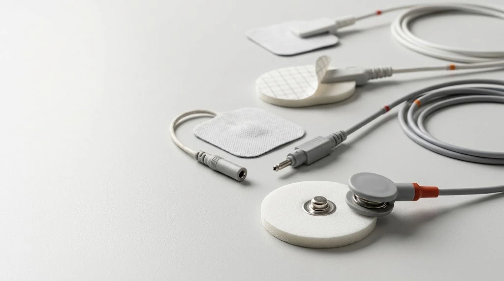
Quick Answer: What Are the Main Types of Medical Electrode Connectors?
Medical electrode connectors are interfaces that connect an electrode to a compatible electrical device or lead wire.
Common connection designs include:
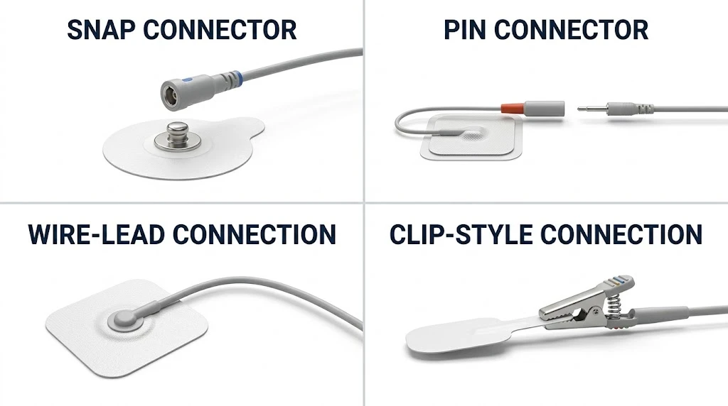
- Snap connectors: A press-fit or snap-style connection commonly used with compatible TENS and EMS electrode systems.
- Pin connectors: A pin-based interface used with compatible electrode leads or equipment.
- Wire-lead connections: A connection in which a wire is integrated into the electrode assembly.
- Clip-style connections: A mechanical connection that uses a compatible clip or clamping mechanism.
- Custom connectors: Application-specific interfaces designed around a device's electrical, mechanical, and product integration requirements.
These categories describe general connection approaches rather than a universal classification standard. Actual connector designs vary by product and manufacturer.
The correct choice depends on the intended device, mating interface, electrical requirements, mechanical design, and intended use. A connector should not be selected based on appearance alone.
1. Why Does the Connector Matter in Medical Electrode Design?
An electrode must do more than provide a conductive interface with the body. It must also establish a suitable electrical connection with the device that drives or measures the signal.
The connector forms part of this overall system.
A poorly matched connection may create mechanical instability, make installation difficult, or prevent the electrode from connecting to the intended device.
Several factors explain why connector selection deserves attention during product development.
1.1 Device Compatibility
The connector must match the device or lead wire it is designed to work with.
Relevant characteristics may include connector geometry, dimensions, contact arrangement, mechanical retention, and electrical configuration.
A connector that looks similar to another design may still be incompatible.
For OEM/ODM projects, the safest starting point is the actual mating interface and its technical documentation, rather than a general description such as "standard connector."
1.2 Connection Stability
The connection should remain stable under the conditions expected during normal use.
Depending on the application, relevant considerations may include resistance to accidental disconnection, mechanical retention, repeated connection and disconnection, and the effects of ordinary handling.
Connection stability is not determined by the connector alone. The way it is integrated into the electrode structure also matters.
For example, the connector-to-electrode interface may need to withstand the mechanical stresses associated with attaching the lead wire or handling the finished product.
1.3 Electrical Performance
The connector is part of the electrical path between the device and the electrode's conductive interface.
Its contact design and integration should be suitable for the product's intended electrical requirements.
Potential concerns include intermittent contact, excessive connection resistance, poor contact integrity, and unintended changes in electrical behavior.
The applicable evaluation criteria depend on the device, electrode type, and intended application.
A mechanically secure connector should not automatically be assumed to provide adequate electrical performance; both aspects need appropriate consideration.
1.4 Ease of Use
Connector design also influences how easily users can install, remove, and replace electrodes.
For a home-use TENS device, a straightforward connection may help simplify routine operation.
In a clinical setting, ease of handling and efficient electrode replacement may be more important.
The connector should therefore be evaluated within the context of the complete device and its intended users, rather than as an isolated component.
2. Common Types of Medical Electrode Connectors
There is no single connector design suitable for every medical electrode application.
The following overview explains several common connection approaches and the considerations associated with each.
2.1 Snap Connectors
Snap connectors use a mating mechanism in which two components engage through a press-fit or snap-style connection.
They are commonly associated with TENS and EMS electrode systems, although actual designs and compatibility requirements vary.
Potential advantages include:
- A straightforward attachment process
- Convenient electrode replacement
- Compatibility with appropriately designed reusable lead wires
- A familiar connection approach for many electrode-based stimulation products
However, snap connectors are not universally interchangeable.
Their geometry, dimensions, retention characteristics, and electrical configuration must match the intended mating component.
For product developers, it is important to confirm the specific connector design rather than relying on the term "snap connector" alone.
2.2 Pin Connectors
Pin-based connections use a pin and a compatible receiving interface.
Depending on the design, the pin may be part of an electrode assembly, a lead wire, or another component in the electrical connection system.
Pin connectors can provide a compact connection solution, but their suitability depends on the mating interface and the intended application.
Product developers should consider:
- Pin dimensions and geometry
- Contact arrangement
- Mechanical retention
- Electrical contact requirements
- Protection against unintended disconnection
- Compatibility with the intended device or cable
A pin connector should be specified using sufficient dimensional and interface information to avoid ambiguity during sourcing and manufacturing.
2.3 Wire-Lead Connections
In a wire-lead configuration, the electrode incorporates a wire or lead assembly rather than relying solely on a separate detachable connector at the electrode surface.
The external end of the lead can then be designed to interface with the intended device.
This arrangement may be suitable when the product architecture calls for an integrated lead or a dedicated connection configuration.
Important considerations include:
- Wire length and routing
- Strain relief
- Connection integrity
- Insulation and electrical requirements
- Mechanical protection at the wire-to-electrode interface
- Packaging and handling requirements
Because the wire is integrated into the product assembly, changes to its length, construction, or termination may affect more than the connection interface itself.
These factors should be considered when defining the product specification.
2.4 Clip-Style Connections
Clip-style connections use a compatible clip or clamping mechanism to establish a mechanical and electrical interface.
They may be found in certain electrode systems and monitoring applications, depending on the equipment design.
The suitability of a clip connection depends on its intended mating component and the requirements of the application.
Design considerations may include:
- Contact geometry
- Clamping force
- Mechanical retention
- Ease of attachment and removal
- Electrical contact stability
- Compatibility with the electrode's construction
A clip connection should be assessed as part of the complete electrode-device interface, particularly where movement or repeated handling is expected.
2.5 Custom and Application-Specific Connectors
Some medical devices require a connection interface that does not correspond directly to a commonly available connector design.
This may occur when a device has a proprietary interface, a space-constrained enclosure, or a specific integration requirement.
In these cases, connector development may involve coordination between the device manufacturer and the electrode supplier.
The project may require a defined connector drawing, dimensional tolerances, material requirements, electrical interface specifications, and verification criteria.
Custom connector development can provide design flexibility, but it also requires clear documentation and early compatibility evaluation.
Important: The connector types above are general design categories. They are not interchangeable, and the suitability of any connector must be established for the specific product and device.
3. How to Compare Different Electrode Connector Designs
The best connector is not necessarily the smallest, simplest, or most familiar option.
It is the one that meets the requirements of the intended device and application.
The following table provides a practical comparison framework.
|
Evaluation factor |
What to consider |
Why it matters |
|---|---|---|
|
Device compatibility |
Mating geometry, dimensions, and interface configuration |
Helps ensure the electrode can connect to the intended device |
|
Electrical requirements |
Contact integrity and applicable electrical performance criteria |
Supports reliable signal transmission or stimulation |
|
Mechanical retention |
Resistance to unintended disconnection under expected use conditions |
Helps maintain a stable connection |
|
Ease of handling |
Attachment, removal, and replacement requirements |
Influences the user experience |
|
Product integration |
Space, backing structure, wire routing, and assembly requirements |
Determines whether the connector fits the overall design |
|
Durability |
Expected connection cycles and handling conditions |
Helps define appropriate verification requirements |
|
Manufacturing feasibility |
Assembly method, dimensional control, and inspection requirements |
Supports consistent production |
|
Customization requirements |
Connector drawings, approved components, and change management |
Reduces ambiguity during OEM/ODM development |
This comparison should be used as a starting point rather than a universal ranking.
For example, a detachable connector may be appropriate for a reusable lead system, while an integrated wire assembly may better suit a different product architecture.
The selection should follow the actual requirements of the device and electrode system.
4. How Connector Design Affects the Complete Electrode Structure
A connector cannot be evaluated independently of the electrode to which it is attached.
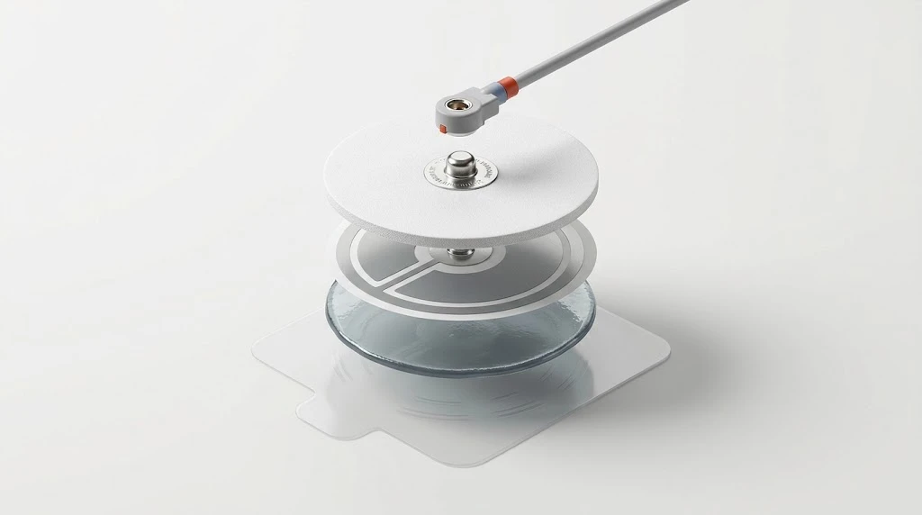
Medical electrodes often contain multiple functional elements, such as a backing material, conductive layer, hydrogel interface, connector, and protective liner.
These components must work together as a finished product.
4.1 Connector Integration With the Backing Material
The backing material provides structural support for the electrode.
Depending on the design, the connector may be mounted on, integrated into, or mechanically supported by part of this structure.
The backing material's thickness, stiffness, flexibility, and construction may influence how the connector can be integrated.
For example, a connector design that works well with one substrate may require additional engineering evaluation when used with a different material or product geometry.
The important question is not simply whether the connector fits. It is whether the connection remains suitable within the complete electrode structure.
4.2 Connector Integration With the Conductive Layer
The connector must establish the intended electrical path to the electrode's conductive components.
The design should provide an appropriate connection while maintaining the required integrity of the surrounding structure.
Potential evaluation areas include electrical contact performance, mechanical attachment, and the effects of assembly processes.
Depending on the product design, the connector interface may require specific inspection or testing to confirm that it meets established requirements.
4.3 Connector Position and Electrode Geometry
Connector position may affect product layout, wire routing, packaging, and ease of handling.
For some applications, available space or the shape of the electrode may constrain the connector's position.
Changing the electrode outline or connector location may therefore require more than a simple drawing update.
The manufacturer should assess whether the change affects assembly feasibility, product dimensions, connection integrity, or other relevant performance characteristics.
4.4 Protecting the Connection During Handling and Storage
The connector is also exposed to handling conditions during manufacturing, packaging, shipping, and use.
The product design and packaging arrangement should account for the connector's shape and any features that could be damaged, bent, contaminated, or placed under unintended stress.
Where relevant, connector protection should be considered during packaging development and finished-product evaluation.
5. What Should OEM/ODM Buyers Specify When Ordering Medical Electrodes?
One common source of product development delays is an incomplete connector specification.
A request such as "TENS electrode pads with snap connectors" may identify the general connection style but leave important technical details unresolved.
Before requesting samples or starting mass production, buyers should provide as much relevant information as possible.
5.1 Identify the Intended Device
Start with the equipment that the electrode must connect to.
Useful information may include:
- Device manufacturer and model
- Existing lead wire or mating connector details
- Device interface drawings, where available
- Known compatibility requirements
- Reference samples of the existing connection
If the device interface is proprietary or not fully documented, an approved physical sample may help clarify the requirements.
A sample should be treated as a reference for evaluation, not as a substitute for necessary technical specifications.
5.2 Provide Connector Drawings and Dimensions
Where possible, supply a technical drawing that defines the mating interface.
Relevant details may include:
- Overall dimensions
- Contact geometry
- Mounting dimensions
- Tolerances
- Material requirements
- Electrical interface details
The necessary information depends on the connector design.
For standard components, an identifiable part number and its controlled technical documentation may be sufficient for some requirements.
Custom interfaces may require more extensive drawings and specifications.
5.3 Define the Complete Electrode Configuration
The connector is only one part of the product specification.
The OEM/ODM manufacturer may also need to know:
- Electrode shape and dimensions
- Backing material
- Conductive interface requirements
- Hydrogel characteristics, where applicable
- Wire configuration, if included
- Packaging format
- Intended device and application
- Applicable performance and acceptance criteria
Providing the complete configuration helps the manufacturer evaluate the connector in the context of the finished electrode.
5.4 Establish Compatibility and Verification Criteria
Before sampling or production, the customer and manufacturer should agree on how compatibility will be assessed.
Depending on the product, this may include:
- Confirmation of the mating interface
- Dimensional inspection
- Mechanical connection evaluation
- Electrical performance testing
- Repeated connection testing, where applicable
- Review of the complete electrode assembly
Not every project requires every test listed above. The verification plan should reflect the product design, intended use, applicable requirements, and identified risks.
The purpose is to establish clear acceptance criteria before the product enters routine production.

6. How Connector Selection Influences OEM/ODM Manufacturing
For OEM/ODM manufacturers, connector selection affects product design, component sourcing, assembly methods, and quality control.
A connector may be readily available as a standard component, or it may require a specific supplier, custom tooling, or dedicated assembly arrangements.
These differences can influence project timelines and manufacturing complexity.
Standard Connectors
Where a suitable standard connector is available, the development process may be more straightforward.
However, the manufacturer still needs to confirm the exact interface, approved component, compatibility requirements, and applicable acceptance criteria.
The term "standard" should not be interpreted as meaning universally compatible.
Custom Connectors
A custom connector may offer a better fit for a specific device architecture, but it usually requires more detailed coordination.
The development process may involve:
- Reviewing device interface requirements
- Confirming dimensions and tolerances
- Evaluating integration with the electrode structure
- Establishing assembly and inspection methods
- Verifying mechanical and electrical performance
- Controlling drawing revisions and approved configurations
The earlier these requirements are established, the easier it is to identify design constraints before they affect sampling or production.
Connector Changes During an Existing Project
Changing a connector after a product has entered production requires a structured assessment.
The change may affect device compatibility, assembly methods, electrical performance, tooling, documentation, or previously completed verification activities.
The manufacturer and customer should determine whether additional evaluation is required and whether customer authorization is necessary before implementation.
This is especially important when the connector forms part of a previously approved product configuration.
7. Common Mistakes When Selecting Medical Electrode Connectors
Several avoidable mistakes can create compatibility problems or unnecessary development work.
Mistake 1: Choosing by Appearance Alone
Two connectors may look similar but differ in dimensions, mating geometry, retention characteristics, or electrical configuration.
Better approach: Confirm the actual mating interface using technical documentation, controlled drawings, or appropriate reference samples.
Mistake 2: Assuming a Connector Is Universally Compatible
A connector description may refer to a general connection style rather than a fully interchangeable interface.
Better approach: Verify compatibility with the exact device, lead wire, or mating component.
Mistake 3: Evaluating the Connector Separately From the Electrode
A connector may fit the device but be unsuitable for the electrode's backing material, structure, or assembly process.
Better approach: Evaluate the connector as part of the complete electrode assembly.
Mistake 4: Ignoring Mechanical Handling Requirements
A connection may work during an initial fit check but behave differently under repeated handling or expected use conditions.
Better approach: Define relevant mechanical requirements and verification criteria based on the product's intended use.
Mistake 5: Leaving Connector Requirements Until Late in Development
Late connector decisions can trigger changes to product geometry, tooling, sourcing, and verification plans.
Better approach: Confirm the device interface and connector requirements during the early design stage.
Mistake 6: Failing to Control Approved Connector Versions
If a component is substituted without appropriate review, the new version may not match the configuration originally evaluated.
Better approach: Maintain controlled specifications and assess connector substitutions through the applicable change management process.
8. How to Evaluate an Electrode Manufacturer's Connector Capabilities
For medical device companies, the ability to manufacture an electrode is only part of the evaluation.
The supplier should also be able to understand the intended device interface, communicate technical requirements, and establish appropriate verification criteria.
Buyers can use the following questions during supplier discussions.
|
Question |
What it helps evaluate |
|---|---|
|
Can you manufacture electrodes with the required connector configuration? |
Product and manufacturing compatibility |
|
Can you review connector drawings and dimensional requirements? |
Technical communication and specification review |
|
How do you verify connector integration with the finished electrode? |
Product-level evaluation capabilities |
|
How are connector components and approved versions controlled? |
Component and configuration management |
|
Can you support custom connector integration for OEM/ODM projects? |
Customization and engineering coordination |
|
How are connector substitutions assessed? |
Change management and continuity of approved configurations |
|
What information is needed before sample development? |
Project readiness and development efficiency |
The answers should be evaluated against the actual needs of the project.
For a product using a familiar connector design, the primary requirement may be accurate integration and verification. For a device with a proprietary interface, technical collaboration and custom design support may be more important.
The goal is to establish whether the supplier can support the specific product rather than simply confirm that it offers connectors in general.
9. How TOP-RANK Healthcare Fits Into Medical Electrode Development
TOP-RANK Healthcare manufactures medical conductive products, including TENS/EMS electrodes and other electrode categories, alongside conductive hydrogel and related materials. Its product portfolio and manufacturing capabilities are described on the company's official website.
For OEM/ODM projects, connector requirements should be considered alongside electrode geometry, conductive materials, backing construction, and the intended device interface.
A clearly defined product specification helps the manufacturer assess the complete assembly, identify compatibility questions early, and establish appropriate verification requirements.
For customers developing customized electrode products, useful starting materials include:
- The intended device or lead-wire interface
- Existing connector drawings or reference samples
- Electrode dimensions and product drawings
- Material and construction requirements
- Intended application and operating conditions
- Applicable acceptance criteria
These details help establish a shared technical baseline before sample development and production planning.
Conclusion: Connector Compatibility Starts With the Complete System
Medical electrode connectors influence more than the physical attachment between two components.
They are part of a larger system that includes the device interface, electrical requirements, electrode structure, assembly process, and intended user experience.
Selecting the right connector requires a clear understanding of the intended application and the technical requirements of the complete product.
For OEM/ODM projects, early communication about connector geometry, dimensions, materials, and verification criteria can help reduce avoidable compatibility issues and support a more efficient development process.
The right connector is not simply the one that fits. It is the one that fits the device, works within the electrode design, and meets the requirements of the complete application.
Frequently Asked Questions
1. What are the most common types of medical electrode connectors?
2. Are all TENS electrode connectors interchangeable?
3. How do I choose the right connector for a medical electrode?
4. Can an electrode manufacturer customize connector configurations?
5. Why is connector integration important in electrode manufacturing?
6. What information should buyers provide when ordering custom medical electrodes?