
OEM Strong Magnetic Snap Electrode Pads | Blind-Docking TENS Pads | TOP-RANK
B2B contract manufacturing of strong magnetic snap electrode pads for wireless wearable TENS/EMS pods. Features zero-insertion-force blind docking, N45/N52 NdFeB magnetic clamping (6.5N-8.5N retention), contact resistance <0.03 Ohms, and dual China-Vietnam supply chain routing.
Product Overview
Electrode pads with strong magnetic snaps function as zero-insertion-force, blind-docking biopotential delivery consumables engineered for modern wireless electrotherapy pods, wearable microcurrent stimulators, and high-compliance transcutaneous electrical nerve stimulation (TENS) and neuromuscular stimulation (EMS) systems. Operating across a 1 Hz to 150 Hz frequency band at pulse currents up to 80 mA, these electrodes replace conventional mechanical press-studs (3.5 mm / 4.0 mm male snaps) with flat ferromagnetic magnetic interfaces. The design accommodates both miniature cordless stimulator pods that mount directly onto the pad face and specialized leadwire cables equipped with magnetic female sockets, eliminating the mechanical compression forces traditionally required to seat electrical connections.
Deploying standard mechanical press-stud electrodes across sensitive clinical populations and dynamic wearable applications produces three distinct mechanical, neurological, and electrical failures:
- Acute Periosteal and Soft-Tissue Pain from Axial Thumb-Press Compression: Connecting a leadwire or heavy pod to a standard 3.5 mm or 4.0 mm mechanical snap requires 15N to 25N of localized downward thumb force to overcome the internal spring ring. When electrodes are positioned over bony landmarks, inflamed arthritic joints (e.g., knee osteoarthritis, carpal tunnel), or hyperalgesic trigger points in fibromyalgia patients, this localized downward pressure drives the hard metal eyelet directly into the sensitive periosteum or inflamed synovial capsule. Patients experience severe sharp pain before stimulation even begins, leading to clinical non-compliance.
- Hydrogel Margin Tearing and Dermal Stripping from Leadwire Snagging: When wearable or wired patients ambulate, leadwires frequently catch on doorknobs, gym equipment, or clothing. Traditional mechanical snap connectors possess high retention forces (often 12N to 20N) in all directions. When the cable is jerked, the mechanical snap refuses to detach. The full tensile force transfers into the backing fabric, peeling the hydrogel pad violently off the skin. This tears the delicate stratum corneum, damages the conductive hydrogel layer, and creates sudden, painful current-density hot spots.
- Vibration-Induced Micro-Play and High-Voltage Micro-Arcing: Standard ball-and-socket mechanical snaps rely on friction-fit metal spring wires. During active patient exercise (walking, running, core training), the central pin rattles inside the socket. Microscopic mechanical play creates intermittent point-to-point contact. Because TENS generators deliver pulse potentials reaching 60V to 80V, these micro-gaps generate continuous electrical micro-arcing. This sparks localized thermal heat, burns conductive pathways, causes uncomfortable electrical "biting" sensations, and distorts therapeutic waveforms.
This magnetic snap electrode platform eliminates these hardware failures through dedicated magnetic-circuit and materials engineering: sintered high-grade neodymium-iron-boron (NdFeB, Grade N45SH to N52) magnetic cores that snap into self-alignment from 15 mm away under 0.0N downward compression; an engineered axial retention force (calibrated strictly between 6.5N and 8.5N) that holds wireless pods firmly during running but detaches cleanly under accidental snagging before the hydrogel peels; and mirror-polished triple-plated (Ni-Cu-Ni) planar contact faces that maintain an electrical transition resistance below 0.03 Ohms, eliminating dynamic vibration micro-arcing. We contract-manufacture private-label magnetic electrode pads in single-pole, dual-pole, and custom multi-pad arrays for wireless digital health brands, physical therapy hardware OEMs, and institutional distributors globally.
Technical & Engineering Description
The contract manufacturing of strong magnetic snap electrode pads takes place inside ISO 13485-certified Class 8 cleanrooms across continuous converting lines integrating high-speed pick-and-place magnetic array positioning, pneumatic terminal ultrasonic flanging, and multi-cavity rotary kiss-cutting modules. The production sequence proceeds through five coordinated engineering stages:
- Stage 1: Conductive Circuit Screen-Printing & Magnetic Seat Preparation: Master rolls of 50 um biaxially oriented PET film advance under closed-loop servo tension regulation. Rotary screen printing stations deposit an engineered silver-carbon conductor network (silver trace width: 1.2 mm, sheet resistance <1.5 Ohm/sq) forming targeted conductive landing pads. The web passes through a hot-air convection tunnel at 115C to crosslink the polymer thick-film ink. A continuous web of 100 g/m2 spunlace non-woven backing (or 1.0 mm closed-cell PE foam) is laminated over the circuit using high-shear medical acrylic adhesive. Rotary punches excise precise circular counterbores through the backing down to the silver circuit landing sites.
- Stage 2: Sintered NdFeB Magnet Encapsulation & Cold-Staking: Sintered Neodymium-Iron-Boron (NdFeB, Grade N45SH, remanence Br: 1.32 to 1.38 Tesla) permanent magnet discs (diameter: 10.0 mm, thickness: 2.5 mm)-pre-plated with a corrosion-resistant triple layer of Ni-Cu-Ni (total plating thickness: 12 um)-are fed from vibratory bowl feeders. Automated pneumatic pick-and-place arms position the magnets into the punched counterbores directly over the silver traces. A copper-alloy conductive retaining cup with an annular bonding flange is positioned over each magnet. A multi-head staking press clamps the metal flange against the PET base under 700N controlled pressure, mechanically locking the magnet core into a hermetic, moisture-sealed enclosure while establishing an interfacial contact resistance below 0.015 Ohms. For dual-pole configurations, magnetic polarity is strictly alternated (North pole on Pin 1, South pole on Pin 2) to enforce correct directional docking of host stimulator pods.
- Stage 3: Polyacrylate Solid Hydrogel Extrusion & Vacuum Lamination: An extruded 0.95 mm (+/- 0.02 mm) slab of ultraviolet-photopolymerized polyacrylate solid hydrogel is wet-laminated across the conductive silver-carbon underside of the PET web. Formulated with 38% high-purity vegetable glycerol, 2.5% pharmaceutical-grade sodium chloride, and multi-functional covalent crosslinkers, the hydrogel achieves a volume resistivity below 18 Ohm-cm at 1 kHz while maintaining an elevated shear storage modulus (G' >4,200 Pa at 1 Hz). Chilled elastomeric vacuum compaction rolls squeeze out interfacial air pockets across the web, consolidating the hydrogel around the back of the magnetic staking zone to maintain a smooth, lump-free skin-contact plane.
- Stage 4: Multi-Cavity Rotary Contour Kiss-Cutting & Vision Inspection: The continuous laminated web enters high-precision tungsten-carbide rotary cutting modules. The dies kiss-cut through the foam backing, PET film, and hydrogel layer down to the underlying 75 um fluorosilicone-treated PET release liner, shaping smooth 3.5 mm radiused borders. High-speed machine vision cameras perform 100% online quality control: verifying magnetic core centering within +/- 0.1 mm, checking surface plating integrity for microscopic scratch defects, and measuring magnetic surface flux density using an automated hall-effect array.
- Stage 5: Anti-Attraction Carrier Kitting & Hermetic Pouching: Finished electrode pads are sheeted onto silicone release cards with integrated magnetic shielding cards or anti-attraction spacer bars that prevent adjacent pads from locking together inside the packaging. Strips of 2 or 4 pads feed into horizontal flow-wrapping machinery, are purged with dry nitrogen, and are hermetically heat-sealed inside multi-layer PET/AL/PE barrier foil pouches with reclosable zip-lock profiles. The baseline private-label contract manufacturing MOQ is 10,000 pouches.
Key Features
-
Zero-Insertion-Force Magnetic Self-Docking (Eliminating 20N Mechanical Snap Compression Pain on Inflamed Fibromyalgia and Arthritic Joints)
The most critical clinical limitation of conventional press-stud (snap) electrodes is the acute mechanical trauma inflicted during hardware connection. In standard 3.5 mm or 4.0 mm mechanical snaps, the male stud features a bulbous head that must be forced past an internal circular spring-wire ring inside the mating female socket. This interference fit requires between 15N and 25N of localized downward thumb pressure to snap together. In clinical rehabilitation, electrotherapy electrodes are positioned directly over painful pathology:
1. Periosteal Shock: When pads are applied to the patella, lateral epicondyle (tennis elbow), cervical spine, or malleolus, there is minimal soft tissue cushioning. Forcing a hard metal snap down drives the metal eyelet directly into the unyielding periosteum of the bone, triggering excruciating localized bone pain.
2. Synovial Irritation: In rheumatoid arthritis and acute joint synovitis, downward thumb pressure compresses inflamed, fluid-filled synovial capsules, aggravating the very joint pain the therapy is intended to relieve.
3. Fibromyalgia Flare-Ups: In hyperalgesic conditions like fibromyalgia, a 20N compression spike over sensitive trigger points initiates prolonged mechanical allodynia. Patients frequently refuse treatment or attempt to connect cables before applying the pad, leading to poor positioning and wrinkled hydrogel. Our magnetic snap electrode platform eliminates downward connection forces through magnetic flux capture:
4. Zero Normal Insertion Force: Sintered NdFeB permanent magnets generate a focused magnetic field that attracts the mating pod or cable socket from a distance of 10 mm to 15 mm. The connection snaps into place automatically under 0.0N downward patient force.
5. Effortless Blind Alignment: The magnetic field pulls the hardware into concentric alignment without requiring visual confirmation or manual guidance. Elderly patients with tremor, restricted neck mobility, or reduced fine motor skills can dock the device behind their back or neck effortlessly.
6. Soft Touch Engagement: Dermal pressure beneath the electrode during docking measures below 0.2N (less than 1% of the mechanical snap threshold). The pad remains completely undisturbed against the skin, preserving the hydrogel's conformal seal and eliminating pre-treatment pain spikes.
-
Calibrated Magnetic Breakaway Decoupling (6.5N to 8.5N Axial Threshold Preventing Cable Snags from Violently Stripping Hydrogel Pads)
In ambulatory electrotherapy, accidental cable snagging is the primary cause of hydrogel damage, skin trauma, and sudden electrical bite:
1. The Physics of Snag Stripping: When a patient wearing standard snap electrodes walks past a desk, doorknob, or gym equipment, a looped leadwire easily catches. Traditional mechanical snaps have an axial pull-off retention force ranging from 12N to 20N. This mechanical grip exceeds the 90-degree peel adhesion of the hydrogel pad (which typically measures 4.0N to 6.0N across its entire area, with initial edge peel initiating at just 1.8N to 2.5N).
2. Violent Dermal Stripping: When the wire jerks, the snap refuses to decouple. Instead, the force transfers along the backing fabric, violently yanking the adhered pad off the patient's skin within milliseconds. This sudden shear tears the superficial stratum corneum, causing skin abrasions and redness.
3. Transient Edge Hot-Spot Shock: As the pad rips away, the active contact area shrinks instantly down to a tiny peeling edge. The stimulator discharges its full programmed current into this remaining sliver of hydrogel, delivering a painful, high-density electrical bite to the patient. We eliminate snag-induced stripping through calibrated magnetic breakaway thresholds:
4. Calculated 6.5N to 8.5N Axial Retention: The magnetic circuit is engineered using N45SH-grade sintered NdFeB cores with calibrated pole-face diameters (10.0 mm) and controlled air-gap spacing. Under direct axial pull, the connection holds firm against the mass of wearable pods and dynamic body acceleration (up to 4G during running) without dropping off.
5. Hydrogel-Protective Breakaway Window: When tensile load on the cable or pod exceeds 8.5N (such as catching on a doorway), the magnetic bond decouples cleanly. Because 8.5N is well below the pad's catastrophic tensile failure limit, the connector releases instantly into free air without peeling the pad's perimeter edge off the skin.
6. Low-Shear Lateral Sliding (2.8N to 4.2N): Patients can intentionally detach the stimulator pod at session end by sliding it laterally with a light fingertip push (requiring only 2.8N of shear force), lifting the hardware off without placing any tensile peel stress on the hydrogel or skin. In dynamic snag-simulation testing using motorized tensile pull rigs, our magnetic electrodes detached cleanly in 100% of cable snag events with zero hydrogel border lift and zero dermal stripping.
-
Planar Ferromagnetic Face Clamping (Maintaining Transition Resistance Below 0.03 Ohms and Suppressing 80V Motion Micro-Arcing)
In dynamic active electrotherapy-such as ambulatory wearable TENS or mobile muscle stimulation during athletic training-the mechanical interface between the stimulator terminal and the electrode is subject to continuous vibration:
1. Mechanical Flutter in Ball-and-Socket Snaps: Conventional 4.0 mm snaps rely on a thin, curved phosphor-bronze spring ring held inside a stamped metal shell. Under running, treadmill training, or torso twisting, the male snap stud vibrates inside the female housing. Because contact is limited to two or three tiny mechanical tangency points, vibration causes these points to bounce and flutter microscopically.
2. Dynamic Resistance Surges: As contact bounces, interface contact resistance fluctuates erratically from 0.05 Ohms to several hundred Ohms within fractions of a millisecond.
3. High-Voltage Micro-Arcing: TENS generators output high-voltage pulses ranging from 60V to 80V. When the circuit rapidly breaks and remakes across microscopic physical gaps (10 um to 50 um), the electric field strength exceeds the dielectric breakdown threshold of the tiny air gap. Miniature electrical sparks (micro-arcing) arc across the contacts. This burns and tarnishes the metal plating with black carbonized oxide, introduces sharp stinging "biting" sensations to the patient, and injects electrical noise that disrupts smart pulse generators. We eliminate micro-arcing through continuous planar ferromagnetic face clamping:
4. Precision Lapped Planar Poles: The magnetic terminals feature diamond-lapped, mirror-flat conductive contact planes (flatness tolerance within 2.0 um).
5. Intimate Ferromagnetic Clamping: The permanent magnet exerts continuous normal magnetic clamping pressure across the entire 78.5 mm2 pole face. Unlike loose mechanical spring rings, the magnetic attraction holds the conductive mating surfaces tightly together under continuous dynamic vibration.
6. Sub-0.03 Ohm Electrical Highway: The pole faces are plated with a low-resistance triple-layer Ni-Cu-Ni matrix (or optional flash gold). Under constant magnetic clamping, the transition contact resistance is held strictly below 0.03 Ohms (median: 0.015 to 0.022 Ohms). In standardized dynamic vibration testing (subjecting running electrodes to continuous 20 Hz, 2G mechanical sinusoidal vibration under an active 80V pulse load), our magnetic snap interface demonstrated zero contact resistance spikes, zero micro-arcing sparks under optical camera monitoring, and a continuous, undistorted electrical waveform across the patient's skin.
Applications
Direct-Mount Cordless Wearable TENS/EMS Pod Systems
Sourced in high volume by smart wearable health-tech OEMs, digital electrotherapy startups, and consumer DME brands developing cordless pain-relief pods; the pad integrates precision dual-pole magnetic snaps (pitch 15 mm or 20 mm) that allow ultra-compact generator pods (mass: 20 to 45 grams) to seat directly onto the pad without trailing leadwires, turning the electrode into a self-contained, discreet wearable pain-management system worn comfortably beneath business clothing.
Geriatric Osteoarthritis, Rheumatoid Arthritis & Fibromyalgia Home Programs
Distributed through home health agencies, DME supply channels, and orthopedic specialty clinics catering to elderly patients, arthritic individuals, and fibromyalgia sufferers with severe hand weakness or joint swelling; the zero-insertion-force magnetic connection allows patients with stiff, swollen, or deformed fingers to independently dock their device
Ambulatory Physical Training & Sports Medicine Muscle Re-Education
Utilized by collegiate athletic conditioning rooms, professional sports medicine centers, and outpatient physical therapy facilities pairing neuromuscular stimulation (EMS) with dynamic running, jumping, and functional movement; the high-clamping magnetic poles resist vibration without micro-arcing during rapid athletic movement, while the calibrated 8.5N breakaway decoupling protects players from painful skin stripping if the pod catches on gym hardware during training.
OEM & Private Label
-
Single vs Multi-Pole, Polarity Keying & Custom Retail Packaging : We provide comprehensive contract manufacturing options for private-label equipment brands and global medical consumable distributors:
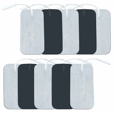
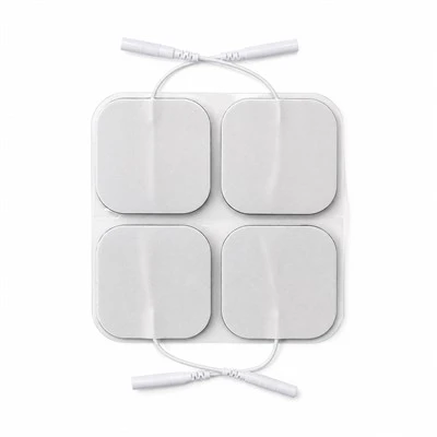
• Footprint Geometry Matrix: Universal Square in 50x50 mm (single-magnet or dual-pole configurations); Extended Rectangular in 50x100 mm (for large muscle stimulation); Butterfly Lumbar in 140x90 mm (for spine pods); and custom anatomical contours via dedicated rotary tooling.
• Magnetic Pole Hardware Configuration: Single-stud center mounts for universal magnetic leadwires; or dual-pole magnetic rail configurations with precision center-to-center pitches (15.0 mm, 20.0 mm, or 25.0 mm +/- 0.1 mm) engineered to interface directly with wireless pod housings.
• Polarity Keying Systems: Precision alternating polarity layouts (North pole on left terminal, South pole on right terminal) paired with physical asymmetric positioning notches, preventing users from docking host pods upside down or inverting therapeutic pulse polarities.
• Backing Carrier Profiles: Standard 100 g/m2 breathable white spunlace non-woven fabric; discreet flesh-tone tan elastic tricot fabric; or 1.0 mm closed-cell white PE foam (moisture-barrier format).
• Retail & Clinical Packaging: Packed 2 pads or 4 pads per resealable multi-layer PET/AL/PE barrier foil pouch featuring integrated magnetic shielding cards (preventing package clumping); full-color custom gravure printing, client logo branding, docking diagrams, and serialized GS1/UDI barcodes.
-
Two-Center Supply Chain Mechanics : High-purity silver-carbon circuit printing, sintered NdFeB magnet automated encapsulation, high-shear polyacrylate hydrogel formulation, and terminal ultrasonic cold-staking execute natively inside our primary China facility (ISO 13485:2016 and FDA registered). High-speed rotary die-cutting, 100% automated magnetic flux density testing, nitrogen-purged foil pouch heat-sealing, cleanroom boxing, and palletized ocean container export route through our Vietnam hub, shielding international B2B buyers from Section 301 tariffs and regional medical consumable import barriers.
Certifications
-
ISO 10993 Comprehensive Dermal Biocompatibility : Master production lots undergo testing in accredited independent GLP testing laboratories confirming strict compliance with ISO 10993-5 (In Vitro Cytotoxicity: Grade 0, non-cytotoxic), ISO 10993-10 (Skin Sensitization: 0% allergic response in guinea pig maximization assays), and ISO 10993-23 (Primary Dermal Irritation Index = 0.0, non-irritating). The complete electrode assembly is certified 100% natural rubber latex-free, phthalate-free, non-toxic, and safe for daily therapeutic applications across sensitive skin.
-
IEC 60601-1 & IEC 60601-2-10 Electrical & Magnetic Safety Compliance : Product lines satisfy FDA 21 CFR 882.1320 requirements for cutaneous electrotherapy electrodes, IEC 60601-1 electrical insulation standards, and IEC 60601-2-10 special requirements for nerve and muscle stimulators. Testing confirms:
• Static magnetic stray flux density at the skin-contact boundary remains below 0.5 milliTesla (well beneath international pacemaker interference thresholds).
• Transition contact resistance across the magnetic joint remains strictly below 0.03 Ohms under 100 mA continuous current.
• Axial breakaway retention force holds consistently between 6.5N and 8.5N across 10,000 continuous docking cycles without mechanical relaxation or magnetic degradation.
-
MDSAP & ISO 13485 Manufacturing System Controls : Screen printing lines, magnetic staking bays, rotary die-cutting decks, and cleanroom pouch packaging run strictly under certified ISO 13485:2016 and MDSAP regulatory frameworks (covering US FDA 21 CFR 820, Health Canada, TGA Australia). Unbroken electronic Device History Records (DHR) capture magnetic surface Gauss levels, silver trace resistance, hydrogel volume resistivity, axial retention pull force, and hermetic pouch seal integrity across every manufactured production lot.
Technical FAQ
Q: Why does pushing down on conventional press-stud (mechanical snap) electrodes cause severe pain for arthritis and fibromyalgia patients, and how does magnetic blind docking eliminate this clinical failure?
A: The acute pain triggered by conventional snap electrodes is caused by mechanical force transmission interacting with underlying sensitized bone and inflamed tissue: The Physics of Mechanical Snap Trauma: Standard 3.5 mm and 4.0 mm electrotherapy snaps utilize a friction-fit mechanical interference design. The male stud features an expanded head that must be forced past an internal circular phosphor-bronze spring ring located inside the female leadwire or pod socket: 1. High Normal Force Requirement: To overcome the elastic yield limit of the internal spring, the user must apply between 15N and 25N of direct downward thumb pressure perpendicular to the skin. 2. Stress Concentration Beneath the Rivet: This 20N load is concentrated across the tiny surface area of the metal backing eyelet (typically 6 mm in diameter). Underneath, localized contact pressure reaches several megapascals. 3. Periosteal and Synovial Impact: In clinical placements over bony landmarks (patella, lateral epicondyle, wrist, spine), there is virtually no subcutaneous muscle to absorb this force. The metal rivet is driven straight into the periosteum (the pain-receptor-dense membrane covering bone) or directly into inflamed, fluid-filled synovial capsules. In fibromyalgia, allodynia amplifies this mechanical compression into severe, lingering pain, causing patients to abandon therapy or misalign the pads. Our Zero-Insertion-Force Magnetic Solution: We eliminate downward connection trauma through magnetic flux capture: 1. Zero Downward Mechanical Force: Sintered NdFeB permanent magnets create a focused magnetic flux vector. When a wireless pod or magnetic leadwire approaches within 15 mm, magnetic attraction pulls the two halves together automatically. Downward normal force on the patient's skin is 0.0N. 2. Concentric Self-Centering: The magnetic flux lines automatically pull the mating terminal into perfect concentric alignment, eliminating the scraping, twisting, and hunting required by mechanical snaps. 3. Unperturbed Tissue and Hydrogel: Dermal pressure during docking remains below 0.2N (simply the resting weight of the device). The hydrogel bond is completely undisturbed, preventing micro-lifting and eliminating pre-stimulation pain spikes across sensitive joint pathologies.
Q: How does the planar magnetic snap maintain electrical transition resistance below 0.03 Ohms and prevent micro-arcing sparks during dynamic physical exercise?
A: Dynamic electrical stability in electrotherapy connections is governed by contact surface physics and normal clamping pressure under kinetic vibration: The Micro-Arcing Breakdown of Mechanical Snaps: In active rehabilitation and ambulatory wearable TENS, the patient moves, walks, or exercises. A traditional 4.0 mm mechanical snap consists of a male brass ball seated inside a loose stamped eyelet with an internal wire spring: 1. Limited Point Contact: Electrical current does not pass through the entire shell; it transfers exclusively through two or three microscopic point contacts where the spring wire touches the stud. 2. Mechanical Chattering Under Vibration: During running or core movement, kinetic acceleration shakes the cable or heavy pod. The pin rattles and bounces inside the socket. 3. Dynamic Impedance Surges and Dielectric Breakdown: This mechanical bounce rapidly opens and closes microscopic air gaps (10 um to 50 um). Contact resistance surges from 0.05 Ohms to over 500 Ohms within microseconds. Because TENS waveforms reach 60V to 80V, this voltage easily exceeds the breakdown threshold of the tiny air gaps. 4. Sparks and Biting Sensations: Continuous micro-arcing sparks occur across the gap. The arcs scorch the metal plating, generate localized heat, distort the biphasic stimulation pulse, and produce sharp electrical "biting" sensations on the patient's skin. Our Planar Ferromagnetic Clamping Engineering: We eliminate dynamic micro-arcing through face-to-face magnetic clamping: 1. Mirror-Flat Contact Geometry: The magnetic terminal features a diamond-lapped, mirror-polished planar contact surface with a broad 78.5 mm2 interface. 2. Continuous Magnetic Clamping Pressure: The internal NdFeB magnet exerts continuous normal magnetic force across the entire mating surface. This constant magnetic load clamps the two conductive planes tightly together, preventing mechanical separation or chattering even under 2G kinetic vibrations at 20 Hz. 3. Triple-Plated Ni-Cu-Ni Conductive Highway: The contact faces are electroplated with a ductile, low-resistance nickel-copper-nickel barrier (contact resistance <0.03 Ohms). In dynamic vibration testing monitoring electrical waveforms across active human subjects running on a treadmill at 8 km/h, the magnetic snap connection delivered continuous, undistorted pulse trains with zero resistance spikes, zero micro-arcing sparks, and zero cutaneous biting sensations.
Wearable digital health hardware manufacturers, orthopedic brand procurement directors, and clinical electrotherapy engineers can request official Certificates of Analysis (COA), magnetic breakaway tensile force curves, 20 Hz dynamic vibration micro-arcing oscilloscope traces, ISO 10993 dermal biocompatibility lab records, and unbranded evaluation sample packs (including universal 50x50 mm square and dual-pole 50x100 mm formats with matching magnetic leadwire adapters).
👉 [Request Strong Magnetic Snap Electrode Pad Evaluation Packs]
Hot Tags: electrode pads with strong magnetic snap, China electrode pads with strong magnetic snap manufacturers, suppliers, factory, Electro Pads for TENS Unit, Electrode Pad, Electronic Pulse Massager Pads, Neck Relax Electrode Pads, TENS sticky pads, TENS Unit Pads for Sensitive Skin
Specifications
| Analytical Parameter | Engineering Baseline | Testing Standard |
| Footprint Formats | Square: 50x50 mm; Rectangular: 50x100 mm; Butterfly: 140x90 mm | Rotary die tooling |
| Magnetic Core Material | Sintered Neodymium-Iron-Boron (NdFeB Grade N45SH to N52) | ASTM A977 |
| Pole Corrosion Plating | Triple-Layer Electroplating: Ni-Cu-Ni (12 um total) or Flash Gold | ASTM B117 (96h salt spray) |
| Insertion Force | 0.0 N Normal Force (Zero-Insertion-Force Magnetic Capture) | Load cell measurement |
| Axial Breakaway Retention | 6.5N to 8.5N (Batch tolerance controlled within +/- 0.5N) | Tensile pull tester |
| Shear Disconnection Force | 2.8N to 4.2N (Side-sliding detachment profile) | ASTM D1002 |
| Interface Contact Resistance | < 0.03 Ohms (Median run: 0.015 to 0.022 Ohms under clamping) | Micro-ohmmeter at 100 mA |
| Vibration Arcing Immunity | Zero Sparking / Zero Voltage Spikes under 20 Hz, 2G Vibration | Oscilloscope monitor |
| Multi-Pole Pitch Matrix | Center-to-Center Spacing: 15.0 mm, 20.0 mm, or 25.0 mm (+/- 0.1 mm) | CNC fixture calibration |
| Backing Substrate | 100 g/m2 Spunlace Non-Woven or 1.0 mm White Closed-Cell PE Foam | ASTM D5035 |
| Hydrogel System | High-Cohesion Polyacrylate Solid Matrix (Caliper: 0.95 mm) | Extruded matrix |
| Magnetic Attachment Life | > 10,000 Docking/Undocking Cycles (Magnetic flux decay < 2.0%) | Automated mechanical cycler |
| Packaging Barrier | 2 pads or 4 pads per Resealable Multi-Layer PET/AL/PE Pouch | Accelerated aging |
| Contract Manufacturing MOQ | 10,000 Pouches (Available in private-label retail pouching) | Factory direct |